- Feedback
- About
- Certificates
- Clientele
- Installations
- Testimonials
- Contact
- Career
- Get Quote


Step-by-Step Calibration Process of Turbine Gas Meters

Saeed Lanjekar
31 Dec, 2025
5 Minutes

Turbine gas meters use a rotating rotor to measure gas flow with strong repeatability and stable performance.
A precise calibration process helps maintain accuracy in industrial setups and supports consistent output in high-demand operations.
This technical guide explains a clear, structured, and practical calibration sequence for a turbine gas meter. It focuses strictly on the calibration workflow and supports readers who want clarity without unnecessary jargon.
For a deeper look at how turbine gas meters function, you may review the working mechanism here: Turbine Flow Meters Working, Benefits & Industrial Uses.
1. Initial Validation Stage
A calibration process starts with a baseline check. Technicians inspect the meter body, rotor, bearings, and internal cavity. They confirm that no physical blockage or wear affects rotation. A clean and stable rotor movement supports a reliable calibration session.
Technicians then review previous records to compare drift or performance issues. This step helps teams decide if the meter needs cleaning, repair, or a full recalibration.
2. Setup of Calibration Bench
The calibration bench creates controlled test conditions. It includes a reference meter, stable gas supply, pressure controllers, and temperature sensors.
The turbine gas meter is mounted on the bench while clamps stabilize the unit. Gas lines connect to the inlet and outlet. Operators verify that no leaks are present and that test instruments are correctly zeroed.
Readers who want to explore how turbine gas meter mechanics work can review this resource:
Turbine Gas Meter Working Principle.
Contact Burak Metering for industry-ready test benches and high-grade turbine gas meters.
3. Pressure and Temperature Alignment
Gas density changes with temperature and pressure. Technicians adjust both parameters to match standard conditions or specific site conditions.
Sensors detect these values in real time. Any drift is corrected before starting the flow test. This step keeps all readings stable and prevents errors caused by density variations.
4. Establishing Reference Flow Levels
The calibration bench creates three or more flow levels:
- Low Flow
- Medium Flow
- High Flow
Each level helps verify meter behavior across the operational range. In many industries, this approach supports reliable readings during both minimal and peak consumption.
For more about how gas flow affects rotor speed, visit out technical guide: How Gas Flow Impacts Turbine Gas Meter Rotation and Accuracy.
5. Running Flow Tests
Gas flows through both the reference meter and the turbine gas meter under test. Readings from each device form the basis for correction. The technician records pulses, volume, and flow rate. If differences appear, the team reviews pressure, temperature, and mechanical drag.
The rotor must spin freely. Bearings must maintain smooth motion. Any irregular motion directly affects reading stability.
- High low
Choose Burak’s precision turbine gas meters for stable performance across diverse flow patterns.
6. Applying Correction Factors
Once the readings are captured, correction factors are calculated. These values adjust meter pulses and convert them into accurate flow data.
Some meters allow digital configuration through onboard electronics. Others require mechanical adjustments. Both approaches aim to match the reference data curve.
Those curious about variations between meter types may check: Mechanical vs Electronic Turbine Gas Meters.
7. Repeating the Test Cycle
After corrections are applied, technicians repeat all flow levels. This confirms that the meter now performs within the acceptable error band.
The cycle continues until every range meets the required accuracy targets. Repeat testing prevents output drift and verifies long-term reliability.
8. Final Verification and Documentation
The final stage includes a full verification of all calibration points. Technicians prepare a report with:
- Error percentage at every flow level
- Correction values
- Pressure and temperature logs
- Bench configuration
- Calibration date and technician initials
This report supports audits, compliance checks, and internal quality control.
Industries across India rely heavily on consistent calibration. Learn more about common applications of turbine gas meters here: Industrial Applications of Turbine Gas Meters in India.
Reach out to Burak Metering for dependable turbine gas meter solutions backed by industry expertise.
Conclusion
A structured calibration sequence helps maintain accuracy and supports smooth operation in industrial gas systems.
Each step, from initial inspection to final documentation, supports reliable flow measurements and reduces downtime.
High-performance turbine gas meters from leading manufacturers help industries maintain consistent readings even under demanding load conditions.
Burak Metering continues to serve as a trusted gas flowmeter manufacturer in India for quality gas meters and calibration support.
For clear guidance and dependable gas flow measurement, reach out to us today.
Share this post


I’m Saeed Lanjekar, founder of Burak Metering. With a background in engineering and technology, I’ve dedicated my career to creating advanced metering solutions that push the boundaries of accuracy and efficiency. At Burak Metering, we’re committed to delivering top-notch technology and driving innovation in the metering industry.
Products
Models
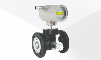
TG-3000
Turbine Gas Meter
- For Natural Gas, LPG, Propane & Non-corrosive gases
- Display: Analog Counter in m3
- Size: DN50 - DN200
- Accuracy: ±1% for 0.2Qmax-Qmax, and ±2% for Qmin-0.2Qmax
- Rangeability: Upto 20:1
- Body: Aluminium, Cast Steel
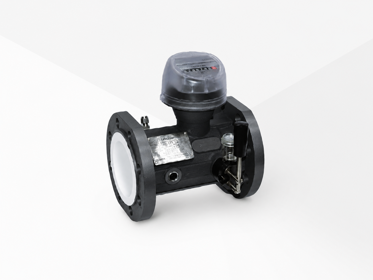
TG-3000-EVC
Turbine Gas Meter with EVC
- For Natural Gas, LPG, Propane & Non-corrosive gases
- Display: Analog + Digital LCD
- Flow unit: SCM, NM3, SCF, KGs
- Size: DN50 - DN200
- Accuracy: +/- ±1.5% for 0.2Qmax-Qmax, and ±3% for Qmin-0.2Qmax
- Output: 4-20mA & RS 485 RTU
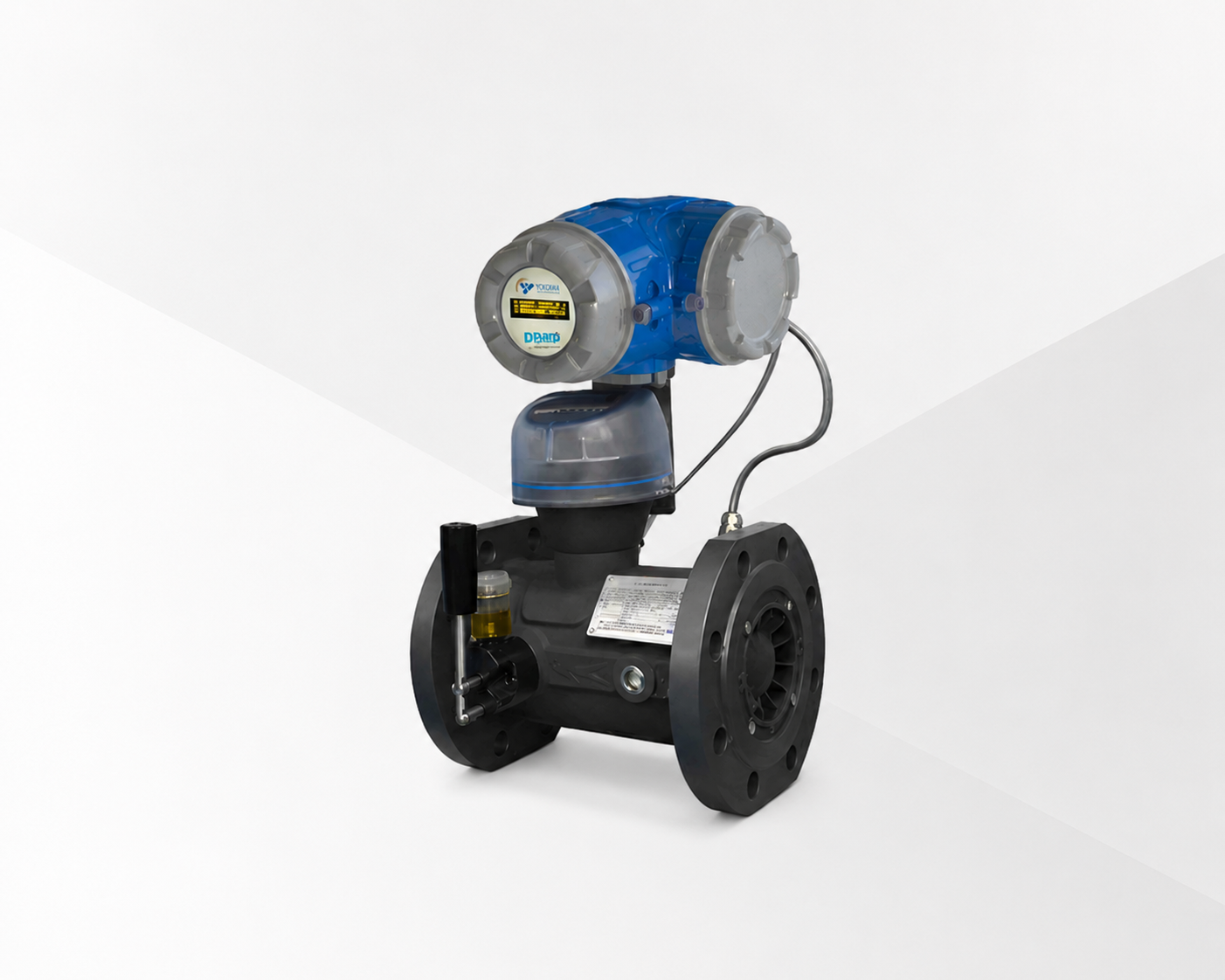
TG-3100-EVC
Turbine Gas Meter with EVC
- For Natural Gas, LPG, Propane & Non-corrosive gases
- Display: Digital OLED
- Flow unit: SCM, NM3, SCF, KGs
- Size: DN25 - DN200
- Accuracy: +/- ±1.5% for 0.2Qmax-Qmax, and ±3% for Qmin-0.2Qmax
- Output: 4-20mA & RS 485 RTU
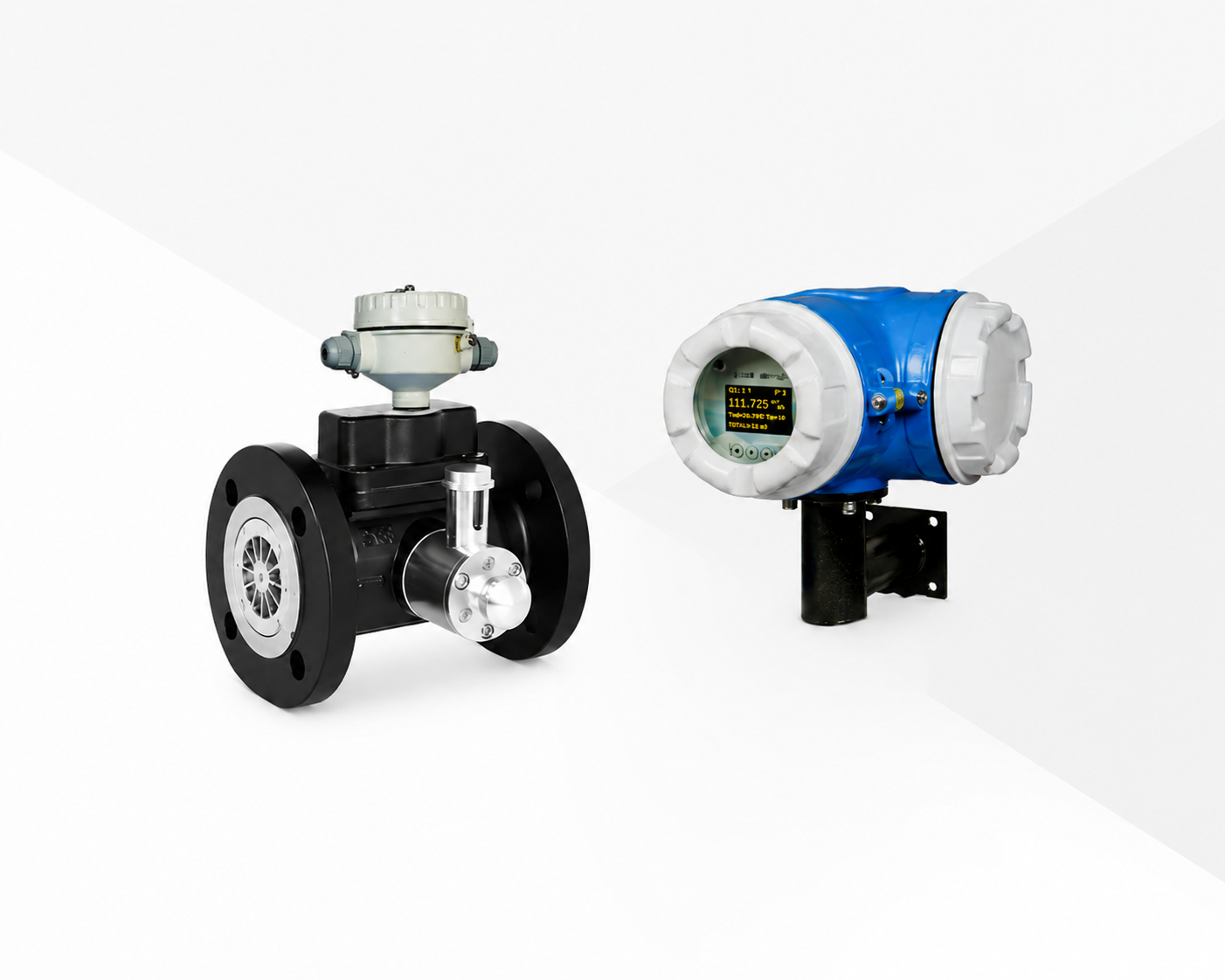
TG-3200
Turbine Gas Meter
- For Natural Gas, LPG, Propane & Non-corrosive gases
- Display: Digital LCD
- Flow unit: Am3, SCM, NM3, SCF, KGs
- Size: DN25 - DN200
- Accuracy: +/- ±1.5% - ±3% of Measured Value
- Output: 4-20mA & RS 485 RTU