 Phone
Phone
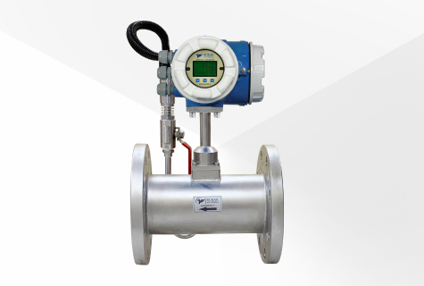
The BX-6010-G Vortex flow meter with built-in temperature and pressure compensation is designed to measure the flow rate of gases or steam within a pipe.
For Dry & Wet Gas, Steam Flow Inbuilt Temperature & Pressure Compensation Pipe Size: 1/2” to 10” 4-20mA HART, RS 485 Modbus, Pulse Temp: 0 ... +120°C & 280°C optionalA BX-6010-G vortex flow meter is a device used to measure the flow rate of gases or steam in a piping system. It operates on the principle that when fluid passes by a bluff body (often a triangular prism), it creates alternating vortices behind the body. The frequency of these vortices is proportional to the velocity of the fluid, allowing for flow rate calculation.
Adding temperature and pressure compensation to a vortex flow meter helps to enhance its accuracy in different operating conditions. Here's an overview of the construction and elements involved:
Vortex Shedding Sensor: The primary component is the vortex shedding sensor, consisting of a bluff body inserted into the flow path. As the fluid flows past this obstruction, vortices are formed. Sensors detect these vortices, measuring their frequency to determine the flow rate.
Temperature Sensor: Incorporating a temperature sensor (often a thermocouple or RTD) allows the meter to account for changes in fluid temperature. This information helps adjust the flow measurement as fluid density and viscosity can change significantly with temperature variations.
Pressure Sensor: A pressure sensor, typically a piezoelectric or strain gauge sensor, measures the pressure of the fluid. This data is used to compensate for changes in pressure, which can affect fluid density and volumetric flow rates.
Microcontroller and Signal Processing: A microcontroller processes the signals from the vortex shedding, temperature, and pressure sensors. Algorithms compensate for temperature and pressure variations, ensuring accurate flow rate measurements.
Compensation Algorithms: Sophisticated algorithms consider the temperature and pressure readings to adjust the flow rate calculation. These algorithms are often based on fluid properties and known equations to correct for changes caused by temperature and pressure.
Display/Output: The meter typically includes a display to show the measured flow rate, totalized flow, and possibly temperature and pressure readings. Output signals (such as 4-20 mA, pulse, or digital communication protocols like Modbus or HART) might be available for integration with control systems.
Enclosure and Housing: The components are housed in a protective enclosure suitable for the operating environment, which could be rugged for industrial settings or more streamlined for commercial applications.
Integrating temperature and pressure compensation in a vortex flow meter provides accurate and reliable flow measurements across varying environmental conditions. This combination ensures that changes in temperature and pressure do not significantly affect the meter's accuracy, making it more versatile for different operational scenarios.
BX-6010-G
Catalog
A thermal mass flow meter is a specialized instrument used to measure the flow rate of gases. It operates by heating a sensor in the fluid's path and…
Learn More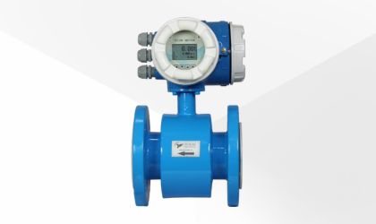
An electromagnetic flow meter is an instrument designed for accurately measuring the flow rate of conductive liquids, such as water or various indust…
Learn More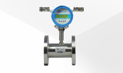
A turbine flow meter is a precision instrument designed to measure the flow of liquids, typically in a pipeline. It operates on the principle of a fr…
Learn More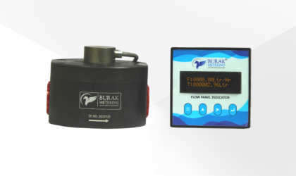
The oval gear flow meter is a precision instrument used to measure liquids' flow rate in various industrial applications. It operates on positive dis…
Learn More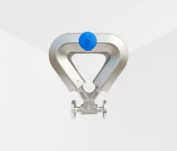
A Coriolis mass flow meter is a highly accurate instrument used to measure the mass flow rate of fluids, including liquids, gases, and slurries. It w…
Learn More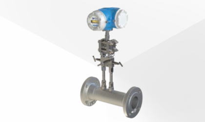
The Burak BV-5000 Series Cone Meters are designed to measure a variety of fluids, including gases, liquids, and vapors. These meters utilize differen…
Learn More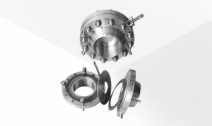
An orifice flow meter measures fluid flow by creating a pressure drop across a precisely machined orifice plate installed in the flow path. As the fl…
Learn More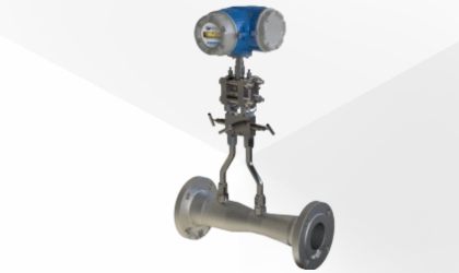
The Burak BN-6000 Series Venturi Flow Meters are designed to measure gases, liquids, and vapors using differential pressure to ensure accurate and re…
Learn More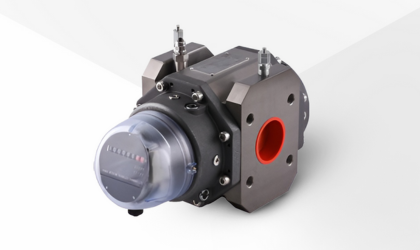
The Rotary Positive Displacement (RPD) Gas Meter is a highly accurate and dependable solution for measuring gas flow across a variety of industrial a…
Learn More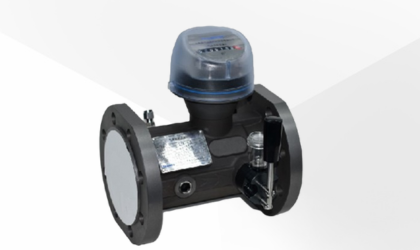
The Turbine Gas Meter is a highly efficient and accurate device designed for gas flow measurement across various industrial applications. It operates…
Learn More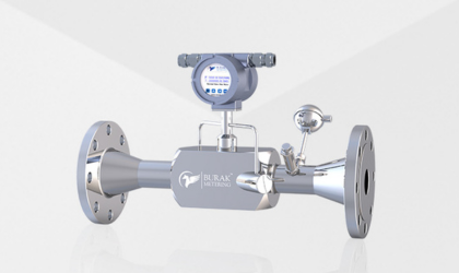
The BU-7010 Series Ultrasonic Gas Flow Meter is a highly accurate solution for measuring gases such as biogas, natural gas, LPG, and propane and othe…
Learn More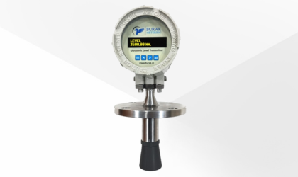
An ultrasonic level transmitter is an innovative device used to gauge the level of liquid or solid substances within a container or tank. With its no…
Learn More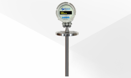
A capacitance level transmitter is a precision instrument that measures levels of liquids, solids, or slurry substances within tanks or containers. I…
Learn More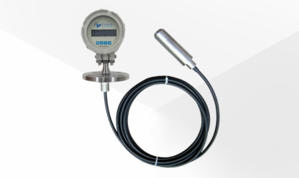
A hydrostatic level transmitter is an instrument used to measure fluid levels within tanks or containers by utilizing the pressure exerted by the liq…
Learn More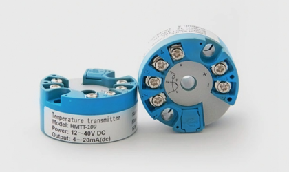
The HMTT-100 Head-Mounted Temperature Transmitter measures temperature and converts it into a standardized analog electrical signal, typically a 4-20…
Learn More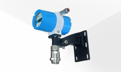
An infrared gas detector is a device used to detect the presence of gases in an area, often as part of a safety system. These detectors can be portab…
Learn More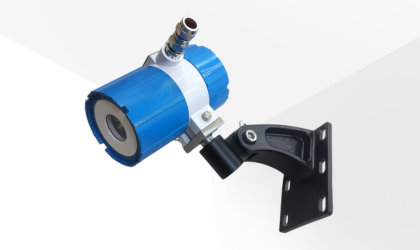
A flame detector is a specialized sensor designed to detect the presence of an open flame by analyzing the radiation emitted during combustion. It pl…
Learn More