Working Principle of Orifice meter
The working principle of an orifice flow meter involves measuring the flow rate of a fluid based on the pressure drop created by an orifice plate installed in the flow path. Here’s a step-by-step explanation:
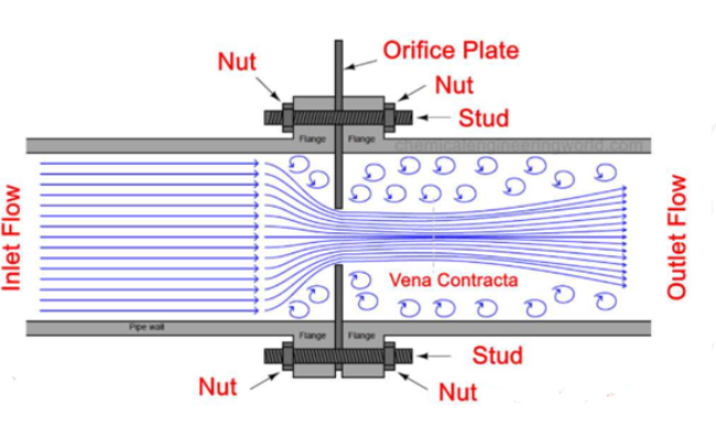
Fluid Flow Introduction: The fluid enters the flow meter and flows towards the orifice plate, which is installed perpendicular to the direction of the flow.
Constriction: The orifice plate has a precisely sized hole (orifice) that constricts the fluid flow, causing the fluid to accelerate as it passes through the opening.
Pressure Drop Creation: The constriction created by the orifice results in a drop in pressure from the upstream side (before the orifice) to the downstream side (after the orifice). The velocity of the fluid increases as it passes through the orifice, leading to a lower pressure downstream.
Pressure Measurement: Pressure taps or sensors are placed before and after the orifice plate to measure the differential pressure created by the flow constriction.
Flow Rate Calculation: The pressure differential between the upstream and downstream taps is used to calculate the flow rate of the fluid. This is based on Bernoulli’s equation and the orifice discharge coefficient, which accounts for the characteristics of the orifice plate and the flow conditions.
Output and Monitoring: The calculated flow rate is then displayed or transmitted to a monitoring system for process control and analysis.
Orifice flow meters provide accurate flow measurements due to the well-understood relationship between pressure drop and flow rate, making them suitable for a wide range of industrial applications.