 Phone
Phone
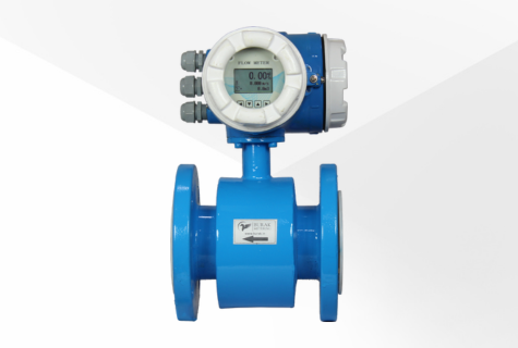
The BE-5000-G Electromagnetic flow meter measures the flow of conductive liquids like water, wastewater, chemicals, etc. The integrated display offers convenient on-the-spot monitoring, simplifying data acquisition and analysis for various industrial applications.
Liquid : Water, Waste water and Chemicals Conductivity: > 5 μS/cm Liner: PTFE & Neoprene Pipe Size: DN15 to DN150 Display: Integral 4-20mA, RS 485 Modbus, Pulse Power supply: 230 VAC Ingress protection: IP 67The construction of an BE-5000-G integral display mount electromagnetic flow meter with a flange connection involves several key components and design considerations.
Integral Display Mount: The flow meter is equipped with an integral display mount, which provides a user-friendly interface for viewing and monitoring flow data. This display typically shows parameters such as flow rate, totalized flow volume, diagnostics, and possibly other relevant information.
Mounting Configuration: The design incorporates a mounting configuration that allows for easy and secure attachment of the flow meter assembly to pipes or other parts of the fluid system. This ensures stability and accuracy in flow measurement.
Materials and Construction: The construction materials are chosen to withstand the specific environmental conditions and the nature of the fluid being measured. Often, these flow meters are made of corrosion-resistant materials such as stainless steel, ensuring durability and longevity even in harsh operating environments.
Electromagnetic Flow Sensor: It consists of a non-intrusive sensor placed inline within the pipe. The sensor generates a magnetic field and measures the induced voltage created by the flow of conductive liquids (like water or chemicals) through the pipe. This voltage is directly proportional to the flow rate and is used to calculate the volumetric flow.
Flange Connection: The flow meter typically features flanged ends, allowing for easy installation and connection to the pipeline. These flanges are designed to meet industry-standard specifications, ensuring compatibility with various pipeline systems.
Sealing and Protection: Proper sealing mechanisms are implemented to prevent leakage and ensure the integrity of the flow meter. Additionally, measures might be in place to protect sensitive electronic components from environmental factors such as moisture or dust.
Electronics and Signal Processing: The flow meter includes electronic components responsible for signal processing, data interpretation, and communication with external systems if required. This might include analog or digital signal processing circuits, microcontrollers, or communication modules.
Calibration and Accuracy: Integral display mount electromagnetic flow meters undergo rigorous calibration processes to ensure accuracy in measuring flow rates across a wide range of operating conditions. Manufacturers often provide calibration certificates or procedures to maintain accuracy.
Maintenance and Serviceability: Design considerations may also focus on ease of maintenance, such as quick access to internal components for servicing or calibration without disrupting the fluid system's operation significantly.
These meters are widely used in various industries, including water treatment, chemical processing, pharmaceuticals, and more, due to their reliability, accuracy, and ability to measure flow in conductive fluids without obstruction in the pipe.
BE-5000-G
Catalog
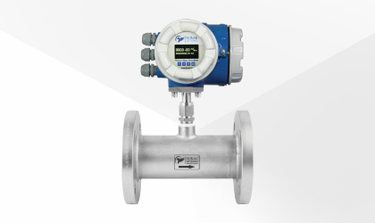
A thermal mass flow meter is a specialized instrument used to measure the flow rate of gases. It operates by heating a sensor in the fluid's path and…
Learn More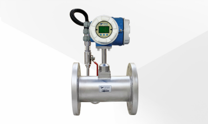
A vortex flow meter is a sophisticated device used to measure the flow rate of fluids, including liquids, gases, and steam, within pipelines or condu…
Learn More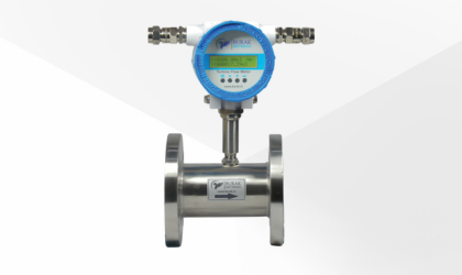
A turbine flow meter is a precision instrument designed to measure the flow of liquids, typically in a pipeline. It operates on the principle of a fr…
Learn More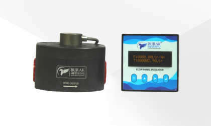
The oval gear flow meter is a precision instrument used to measure liquids' flow rate in various industrial applications. It operates on positive dis…
Learn More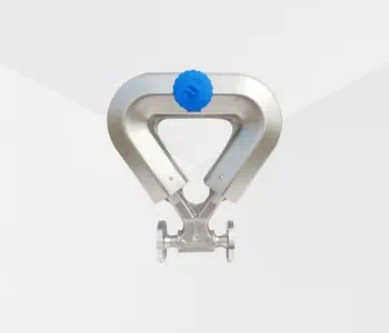
A Coriolis mass flow meter is a highly accurate instrument used to measure the mass flow rate of fluids, including liquids, gases, and slurries. It w…
Learn More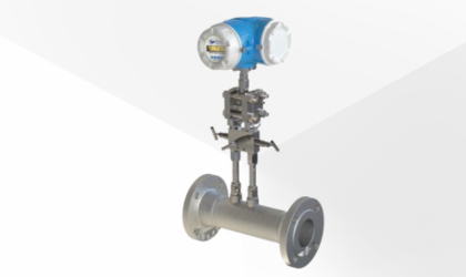
The Burak BV-5000 Series Cone Meters are designed to measure a variety of fluids, including gases, liquids, and vapors. These meters utilize differen…
Learn More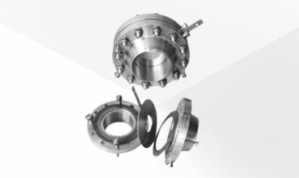
An orifice flow meter measures fluid flow by creating a pressure drop across a precisely machined orifice plate installed in the flow path. As the fl…
Learn More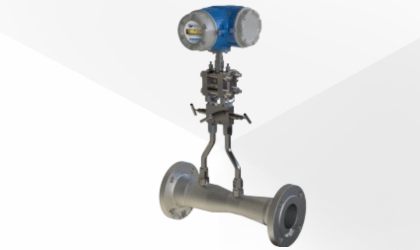
The Burak BN-6000 Series Venturi Flow Meters are designed to measure gases, liquids, and vapors using differential pressure to ensure accurate and re…
Learn More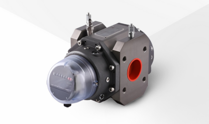
The Rotary Positive Displacement (RPD) Gas Meter is a highly accurate and dependable solution for measuring gas flow across a variety of industrial a…
Learn More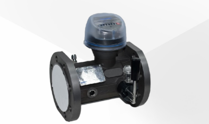
The Turbine Gas Meter is a highly efficient and accurate device designed for gas flow measurement across various industrial applications. It operates…
Learn More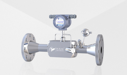
The BU-7010 Series Ultrasonic Gas Flow Meter is a highly accurate solution for measuring gases such as biogas, natural gas, LPG, and propane and othe…
Learn More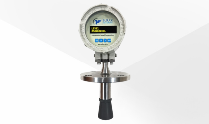
An ultrasonic level transmitter is an innovative device used to gauge the level of liquid or solid substances within a container or tank. With its no…
Learn More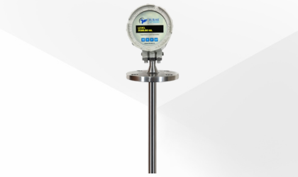
A capacitance level transmitter is a precision instrument that measures levels of liquids, solids, or slurry substances within tanks or containers. I…
Learn More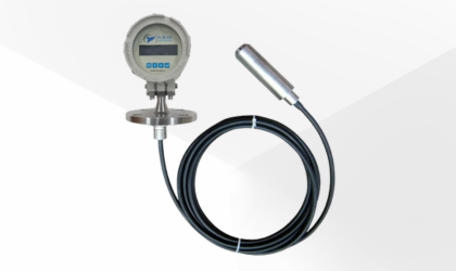
A hydrostatic level transmitter is an instrument used to measure fluid levels within tanks or containers by utilizing the pressure exerted by the liq…
Learn More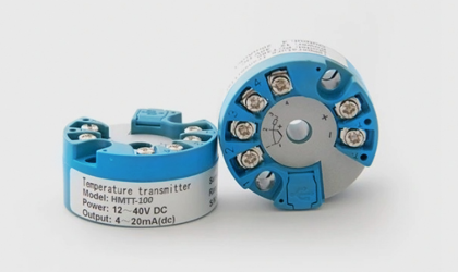
The HMTT-100 Head-Mounted Temperature Transmitter measures temperature and converts it into a standardized analog electrical signal, typically a 4-20…
Learn More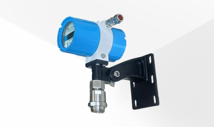
An infrared gas detector is a device used to detect the presence of gases in an area, often as part of a safety system. These detectors can be portab…
Learn More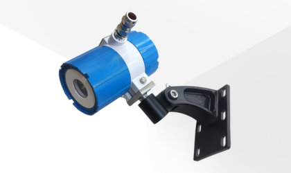
A flame detector is a specialized sensor designed to detect the presence of an open flame by analyzing the radiation emitted during combustion. It pl…
Learn More