- Feedback
- About
- Certificates
- Clientele
- Installations
- Testimonials
- Contact
- Career
- Get Quote


Grounding Requirements for Electromagnetic Flow Meters

Saeed Lanjekar
14 Oct, 2025
6 Minutes
Electromagnetic flow meters (magmeters) measure conductive fluid flow using Faraday’s. The induced voltage is very weak (a few millivolts). Any stray electrical noise or potential difference can distort that signal.
Grounding provides a stable reference potential and a path for unwanted currents, which helps maintain accurate measurement.
This article explains the EM flowmeters' grounding needs, grounding methods, pitfalls, and best practices. Also see related guides on what are electromagnetic flow meters, installation best practices, working principle, and advantages & disadvantages.
Why Grounding Matters
- Weak Signal Sensitivity
The voltage generated by the electrodes is on the order of millivolts or even microvolts at low flows. External potentials or noise can overwhelm the signal. Proper grounding reduces measurement error. - Define Reference Potential
Grounding fixes a reference (zero) potential relative to earth. This ensures that the sensor sees the correct differential voltage. - Divert Stray Currents
Currents from pumps, motors, variable frequency drives, or electrochemical systems can find paths through the flow meter if no grounding is present. A proper ground gives them a safer route. - Safety and Surge Protection
Grounding also helps protect the equipment and personnel from voltage surges, lightning or faults. - Prevent Drift and Noise
Grounding (functional grounding) reduces drift and signal noise, improving stability over time.
Basic Grounding Concepts of Mag Meters
- Protective Ground (PE)
All electrical devices, including the flow converter, must tie into the facility’s safety earth ground. That is required by electrical codes. ( - Functional Ground (FE)
This is the ground for the flow measurement circuit—that links the fluid, electrodes, and sensor, so that the measured voltage is correct. This is often separate from the safety ground. - Ground Loops
Never share the functional ground with power or motor ground paths. That can introduce interference. The meter should have its own low impedance path to ground. - Ground Resistance
Lower resistance is better. Some acts recommend <1 Ω or very low values.
Grounding Methods of EM Flowmeters
Which method you choose depends on pipe material, lining, process fluid, and environment. Here are common methods:
1. Use the metal pipe itself
If the pipe (or flange) is conductive and well earthed, and there is continuous metal-to-metal contact, then the flow meter may not require additional grounding rings. The meter body and electrodes connect electrically to the pipe, forming the path.
However, this works only if:
- The pipe is metallic and well grounded
- The flange and bolts maintain low-resistance contact
- There is no insulating coating or liner interrupting conduction
If any insulation breaks the continuity, you must add another ground method.
2. Grounding Rings (Earth / Ground Rings)
These are metal rings installed on both ends of the meter, between flanges. They make direct contact with the fluid and connect via a conductor to earth. These rings “tap” the fluid to provide the reference.
- Use the same or compatible materials as electrodes to avoid corrosion.
- For abrasive fluids, “protective” or “neck-type” rings may be used to prevent wear.
Grounding rings are almost mandatory when the pipe is non-metallic, lined, or coated.
3. Grounding Electrode / Third Electrode (Reference Electrode)
Instead of rings, you may insert a third electrode in contact with the fluid (beside the two measurement electrodes). This electrode connects to earth via a conductor. It is useful when rings are impractical or too expensive (especially for exotic materials).
One caveat: small potential differences (e.g., 0.2 V) may cause electrolytic damage to the electrode over time.
4. Virtual / Reference Grounding (No Physical Ground)
Some modern converter designs float the input amplifier and generate an internal reference potential that matches the fluid potential. This method avoids direct equalizing currents and overcomes some challenges of external grounding.
This method is ideal when traditional grounding methods are problematic, e.g. lined pipes, cathodic protection, or highly corrosive fluids.
Rules and Recommendations
- The grounding point must be physically and electrically close to the meter to keep impedance low.
- The ground wire should be as short and thick as possible (minimize resistance and inductance).
- Do not share ground with motors, pumps, or power lines. Keep isolation.
- Avoid routing the grounding conductor near large currents, high voltage lines, or sources of interference.
- Inspect grounding periodically to avoid corrosion, loose connections, or damage.
- In systems with cathodic protection, avoid tying the flow meter ground in a way that undermines the protection. The meter should operate as a separate ground entity.
- Use shielded and twisted cable for signal runs; bond the shield at the converter end to ground.
- For surge/lightning protection, ground paths must comply with local electrical codes (e.g., short conductors, adequate cross-section)
Common Problems & Troubleshooting of EM flowmeters grounding
| Problem | Likely Cause | Remedy |
|---|---|---|
| Unstable or drifting reading | Poor or missing functional ground | Add grounding ring or electrode |
| High noise in signal | Ground loop or shared ground | Isolate the meter’s ground path |
| Electrode corrosion | Mismatch of materials or electrolytic currents | Use same materials, inspect electrode, switch method |
| Ground resistance too high | Long or thin ground conductor or poor contact | Shorten, enlarge, improve contact |
| Interference from cathodic protection system | Tangled grounding between systems | Separate the grounding for meter, use isolation |
Some engineers question whether large flange bolts suffice as a ground. The bolts may not touch the fluid or internal conductive path, so they are not reliable as the only grounding path.
Summary
Grounding is critical for electromagnetic flow meters because the induced signal is weak and vulnerable to interference. You need both protective ground (for safety) and functional ground (for measurement accuracy). Depending on pipe material, lining, and environment, you may choose to rely on metal piping, grounding rings, electrodes, or virtual grounding.
Always keep the ground path short, low impedance, and isolated from noisy equipment. Inspect connections routinely. Use shielding, twisted cables, and best practices. Follow local electrical standards. A sound grounding design can prevent most measurement errors and extend meter life.
If you want a reliable electromagnetic flow meter in Mumbai, Burak is your partner. As a top gas flowmeter manufacturer in India, we combine deep engineering know-how with high-quality manufacturing. We test meters under real conditions to guarantee accuracy, stability, and long life. Choose Burak to benefit from turnkey support, prompt service, and trusted performance in demanding applications.
Contact us for your requirements.
Share this post


I’m Saeed Lanjekar, founder of Burak Metering. With a background in engineering and technology, I’ve dedicated my career to creating advanced metering solutions that push the boundaries of accuracy and efficiency. At Burak Metering, we’re committed to delivering top-notch technology and driving innovation in the metering industry.
Products
Models
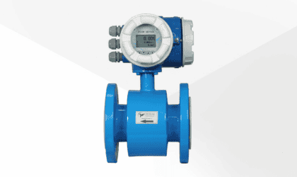
BE-5000-G
Electromagnetic Flow Meter with intergral display
- Liquid : Water, Waste water and Chemicals
- Conductivity: > 5 μS/cm
- Liner: PTFE & Neoprene
- Pipe Size: DN15 to DN150
- Display: Integral
- 4-20mA, RS 485 Modbus, Pulse
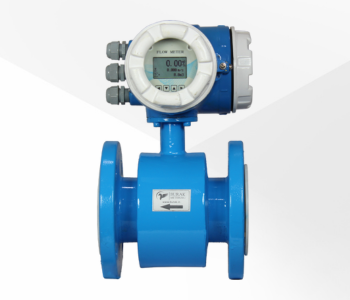
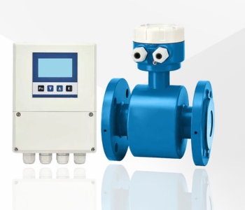
BE-5000-GR
Electromagnetic Flow Meter with remote display
- Liquid : Water, Waste water and Chemicals
- Conductivity: > 5 μS/cm
- Liner: PTFE & Neoprene
- Pipe Size: DN15 to DN500
- Display: Remote with 3 Meter cable
- 4-20mA, RS 485 Modbus, Pulse
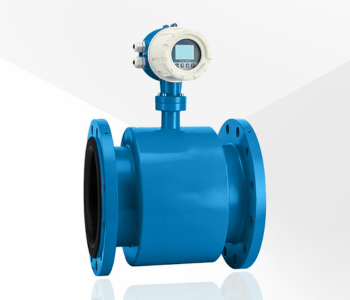
BE-5500-G
Slurry Electromagnetic Flow Meter with intergral display
- Liquid : Slurries & sludges, Effluent, Sewage and Papermaking
- Conductivity: > 5 μS/cm
- Liner: PTFE, Neoprene, Polyurethane & PFA
- Pipe Size: DN15 to DN150
- Display: Integral
- 4-20mA-Hart, Pulse
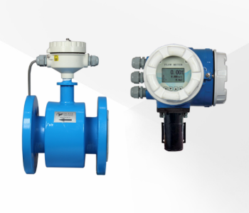
BE-5500-GR
Slurry Electromagnetic Flow Meter with Remote display
- Liquid : Slurries & sludges, Effluent, Sewage and Papermaking
- Conductivity: > 5 μS/cm
- Liner: PTFE, Neoprene, Polyurethane & PFA
- Pipe Size: DN15 to DN500
- Display: Remote with 3 Meter cable
- OUTPUT: 4-20mA-Hart, Pulse