- Feedback
- About
- Certificates
- Clientele
- Installations
- Testimonials
- Contact
- Career
- Get Quote


Working Principle of Electromagnetic Flowmeter

Saeed Lanjekar
24 Sep, 2025
5 Minutes
Electromagnetic flowmeters measure fluid flow by converting the motion of a conductive liquid into an electrical signal.
These devices operate based on Faraday’s law of electromagnetic induction.
By applying a magnetic field across a flowing fluid and capturing the voltage induced, one can determine fluid velocity and then compute volumetric flow.
Would you like to learn more about electromagnetic flow meters? Check our complete guide on what electromagnetic flowmeters are and how they work.
Basic Components of an Electromagnetic Flowmeter
An electromagnetic flow meter has several essential parts:
- A flow tube with an insulating lining.
- Coils or electromagnetic windings that generate a magnetic field across the tube.
- Two electrodes are mounted at opposite sides inside the tube to sense the induced voltage.
- A transmitter or electronics module that converts the sensed voltage into a flow reading and outputs to a control system.
The lining ensures that the induced voltage does not leak into the pipe walls. Materials used for lining vary according to chemical compatibility and physical wear. The electrodes must contact the conductive fluid and resist corrosion or coating.
Physical Principle: Faraday’s Law
Faraday’s law states that when a conductor moves through a magnetic field, it induces a voltage proportional to the velocity of motion, the strength of the magnetic field, and the length (or distance) between the electrodes.
In the case of electromagnetic flow meters:
- The moving conductor is the fluid flowing through the meter.
- The magnetic field is generated by coils surrounding the tube or by external magnetic excitation.
- The electrodes are spaced a fixed distance apart inside the lining. The voltage induced between them is related to that spacing.
The relationship can be expressed as:
E = k × B × V × D
where:
- E is the induced voltage
- B is the magnetic field strength
- V is fluid velocity
- D is the electrode spacing (often equal to internal diameter)
- k is an instrument constant dependent on construction.
Signal Generation and Measurement
When the conductive fluid flows through the magnetic field, charges in the fluid move, creating a potential difference between the electrodes. The stronger the flow (velocity), the larger the induced voltage. The transmitter amplifies and processes that small electrical signal, filters noise, and converts it into a measurable flow rate (volume per time). It may also produce output signals like 4-20 mA or digital communication for control systems.
Often, the magnetic field is pulsed or reversed periodically. This helps cancel out interference voltages and offset errors, such as those from electrode polarization or external electromagnetic noise. By comparing voltages under reversed field polarity, the common disturbances that do not reverse with the field can be subtracted.
Key Conditions for Accurate Measurement
Certain conditions are mandatory for reliable operation:
- Full pipe condition: The flow tube must be filled with liquid. Partial fill or air bubbles disturb the induced voltage measurement.
- Conductivity threshold: The liquid must conduct electricity above a minimum level. Very low conductivity fluids produce too weak signals relative to noise.
- Proper grounding: Since the induced voltages are small, stray currents or external electrical interference can corrupt the signal. Grounding of electrodes or pipe, or the use of grounding rings, is vital.
- Stable magnetic field: The field strength (B) should remain constant or controlled. Fluctuations in magnetic excitation degrade accuracy.
- Correct pipe lining and electrode material: The lining must insulate and resist corrosion or abrasion. Electrode materials (e.g., stainless steel, tantalum, platinum) must suit fluid chemistry.
Advantages of This Principle
- No moving mechanical parts inside the flow path, so wear is low.
- The meter’s reading is unaffected by fluid density, pressure, or viscosity if conductivity is sufficient. This simplifies calibration and reduces error sources.
- Low pressure drop, because the fluid path is unobstructed. That is beneficial for high flow or viscous/slurry liquids.
Limitations or Constraints
- Cannot measure non-conductive fluids such as many oils or gases. The principle fails when the fluid does not carry sufficient ions.
- Low-conductivity fluids may generate a small induced voltage that is difficult to separate from measurement noise.
- Strong external magnetic or electrical interference can degrade the signal unless proper shielding or grounding is used.
- Requirement for full pipe and straight runs upstream and downstream; turbulence or partial flow can introduce error.
Learn More:→ Advantages and Disadvantages of the Electromagnetic Flowmeter
Example: How It Works Step by Step
Imagine water containing dissolved salts flowing through a pipeline fitted with an electromagnetic meter:
- The coils generate a magnetic field through the pipe cross-section.
- Water flows perpendicular to magnetic flux lines.
- Ions in water (charged particles) move under the influence of the flow, causing charge separation across the diameter.
- Electrodes sense a voltage proportional to flow velocity times magnetic field strength.
- The transmitter reads this tiny voltage, filters noise, converts to flow velocity, then multiplies by cross-sectional area to get volumetric flow.
- The output is sent to the display or control system as a standard signal.
Practical Variants & Design Choices
Some designs use pulsed DC magnetic fields to reduce the effects of electrode polarization and drift.
Others include mechanisms for empty-pipe detection (via a reference electrode) to avoid false readings when the pipe is not filled.
Choice of lining (PTFE, PFA, rubber, etc.) depends on fluid corrosivity, temperature, and wear. Electrode technology (material, shape) can adjust response time and durability.
Summary
Electromagnetic flow meters rely on Faraday’s law: moving conductive fluid across a magnetic field induces a voltage. Key parts include coil-field generation, lining, electrodes, and transmitter electronics.
Accuracy depends on a full pipe, adequate conductivity, proper grounding, and a stable field. While this principle brings many benefits like low maintenance and precise flow reading, it also imposes constraints on fluid type, installation, and electrical environment.
Understanding how each component works and what conditions matter allows one to pick or install a meter that delivers reliable performance in the intended application.
Need a reliable electromagnetic flow meter?
As one of the top electromagnetic flow meter manufacturers in India, we deliver high-precision units built for endurance and performance.
Contact us today for a quote or consultation to upgrade your measurement system with our industry-leading flow meters.
Share this post


I’m Saeed Lanjekar, founder of Burak Metering. With a background in engineering and technology, I’ve dedicated my career to creating advanced metering solutions that push the boundaries of accuracy and efficiency. At Burak Metering, we’re committed to delivering top-notch technology and driving innovation in the metering industry.
Products
Models
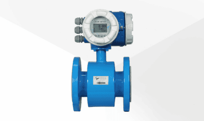
BE-5000-G
Electromagnetic Flow Meter with intergral display
- Liquid : Water, Waste water and Chemicals
- Conductivity: > 5 μS/cm
- Liner: PTFE & Neoprene
- Pipe Size: DN15 to DN150
- Display: Integral
- 4-20mA, RS 485 Modbus, Pulse
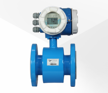
BE-5000-GR
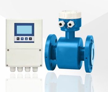
Electromagnetic Flow Meter with remote display
- Liquid : Water, Waste water and Chemicals
- Conductivity: > 5 μS/cm
- Liner: PTFE & Neoprene
- Pipe Size: DN15 to DN500
- Display: Remote with 3 Meter cable
- 4-20mA, RS 485 Modbus, Pulse
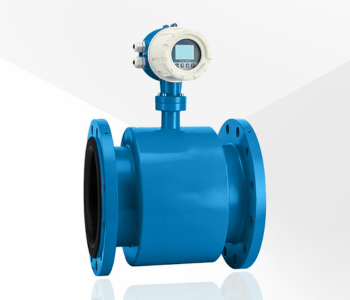
BE-5500-G
Slurry Electromagnetic Flow Meter with intergral display
- Liquid : Slurries & sludges, Effluent, Sewage and Papermaking
- Conductivity: > 5 μS/cm
- Liner: PTFE, Neoprene, Polyurethane & PFA
- Pipe Size: DN15 to DN150
- Display: Integral
- 4-20mA-Hart, Pulse
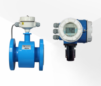
BE-5500-GR
Slurry Electromagnetic Flow Meter with Remote display
- Liquid : Slurries & sludges, Effluent, Sewage and Papermaking
- Conductivity: > 5 μS/cm
- Liner: PTFE, Neoprene, Polyurethane & PFA
- Pipe Size: DN15 to DN500
- Display: Remote with 3 Meter cable
- OUTPUT: 4-20mA-Hart, Pulse