Working Principle of Turbine Flow meter
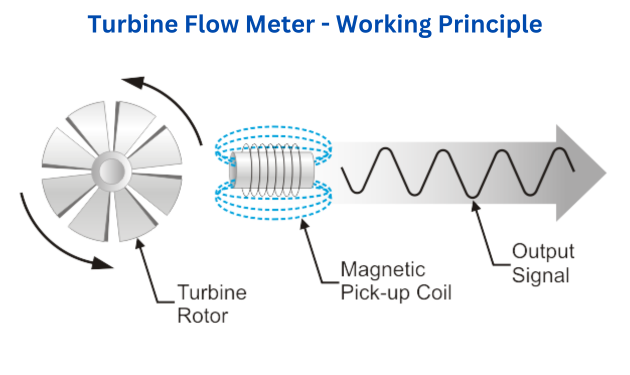
The working principle of a turbine flow meter revolves around the concept of a freely rotating turbine placed within a flowing liquid. Here's a detailed explanation of how it operates:
Fluid Flow: When liquid flows through the pipeline or conduit, it enters the turbine flow meter's housing where the turbine is positioned.
Turbine Rotation: The fluid flow causes the turbine blades to rotate. The number of rotations directly corresponds to the velocity of the fluid passing through the meter. The faster the flow, the faster the turbine spins.
Sensor Detection: As the turbine rotates, it passes a magnetic field generated by embedded magnets or a coil in the meter body. This interaction generates an electrical pulse or signal for each rotation.
Signal Conversion: Sensors within the meter detect these pulses and convert them into an electrical signal proportional to the flow rate.
Measurement and Output: The frequency or number of electrical pulses generated is then translated into flow rate measurements by the meter. These measurements can be displayed locally on the device or transmitted to a remote system for monitoring and control.
Calibration and Accuracy: Turbine flow meters are often calibrated for specific fluids and flow conditions to ensure accuracy. This calibration accounts for variations in fluid properties, ensuring precise measurement outputs.
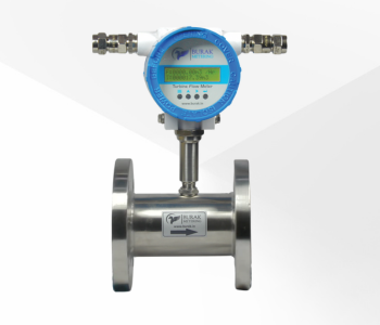
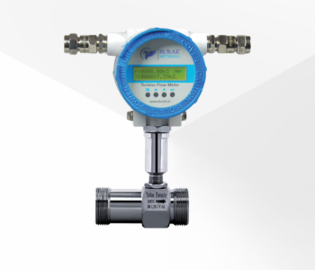
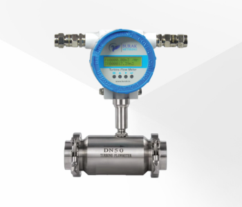
Applications: Turbine flow meters are commonly used for measuring the flow of clean, low-viscosity fluids such as water, fuels & chemicals across various industries due to their accuracy and capability to measure both high and low flow rates.
The turbine flow meter's operation relies on the rotation of a turbine within the flow stream, which generates electrical pulses translated into flow rate measurements, allowing for accurate monitoring and control of liquid flow in various industrial processes.